Update: please note that this posting and some other postings related to this approach to turnout controls are published as originally posted although I've since removed this solution in favor of another approach documented by newer notes. Ultimately, I determined that I was unable to successfully adapt this control system to Z-scale.
The primary reason for this update is to talk about the turnout control design improvements that I've made over the last month.

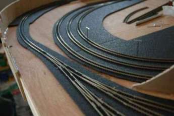
But before that, here are a couple of pics showing some of the progress made on track layout and turnout installations. All 24 turnouts are now in place ... the photo to the left is of the set of turnouts that branch out to the back of the yard.

Here is a straight down view of the installed turnout ... the yellow teflon sleeve is visible with the control wire coming up through it. The wire bends at 90 degrees toward the right and then bends down 90 degrees again through the control loop on the Wright turnout. The top of the teflon sleeve is actually sitting down flush with the top of the roadbed and I believe that I can generally disguise it with ballast in a later step.
A couple of views from underneigh the turnout ... here is where the key improvement has been made.
It turns out that the bellcrank wire tends to ride up in the teflon sleeve and the wire above the turnout will rise up a bit with continued usage. The improvement is to add a spring to the underside that applies downward pressure to keep the wire from rising above. The new spring is positioned over the sleeve as it extends below the layout ... I've had to add some addition pieces of sleeve material to extend below the bend in the wire such that it "locks" in the spring from trying to follow around the bend in the wire. All of the teflon sleeves are held in place with CA glue, taking care not to get any down near where the wire comes out.

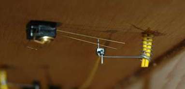
With the mechanical aspects of the linkage now in place, turnout operation appears to be smooth and reliable. I'm glad that I've chosen a bellcrank arrangement for the control as this approach reduces the chance of pushing the points upward. Slow operational movement of the points is easily accomplished simply by moving the cable control lever slowly.
The electrical contact setup visible in these photos is not complete with wiring ... soldering comes later in the process.